For this group assignment we had to:
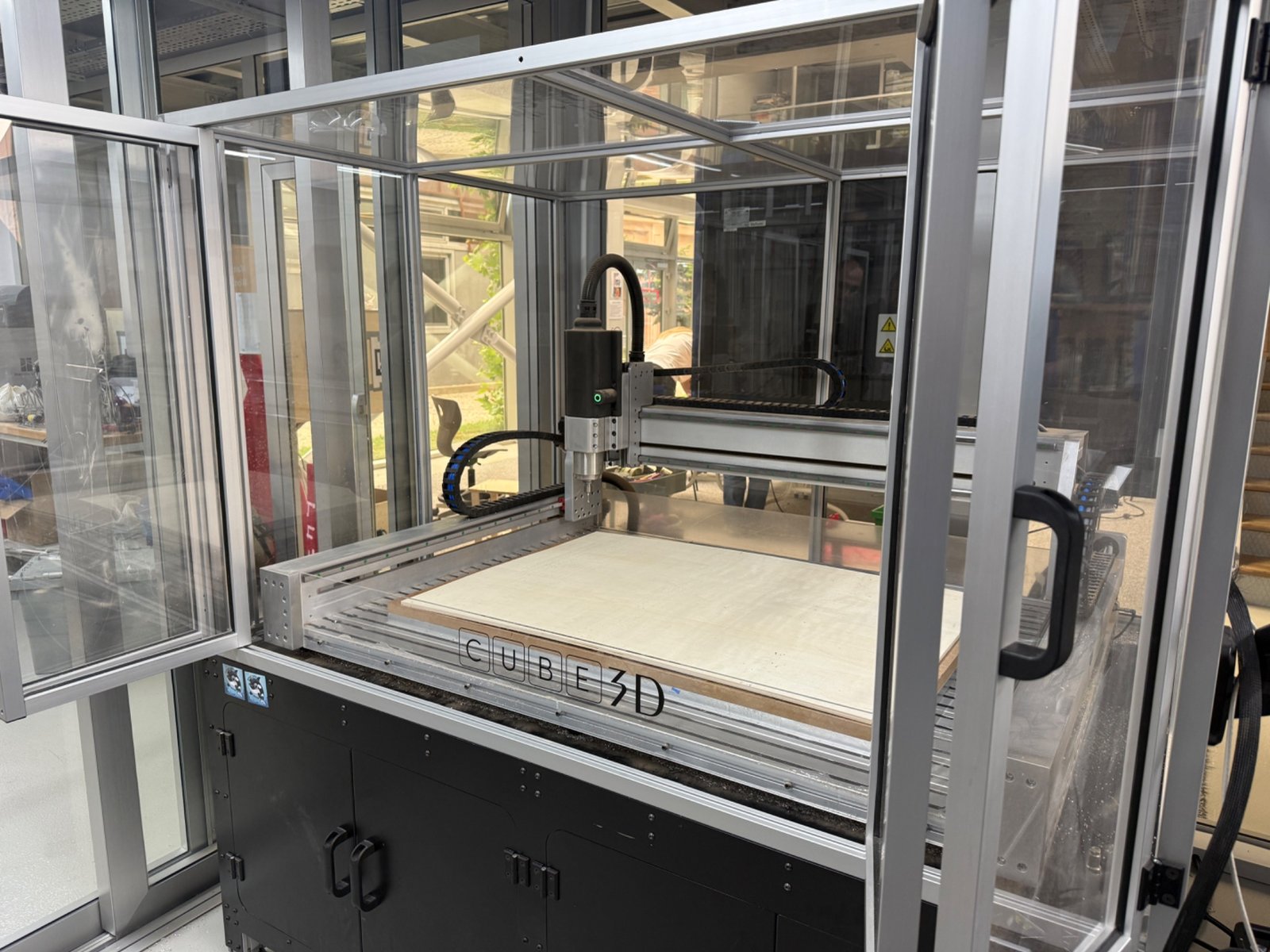
For the characterization tests we used the Derinmotion Cube 3D CNC router in the lab. The test material was 0.8 cm plywood, and the dust was removed with a vacuum cleaner during and after the operation.
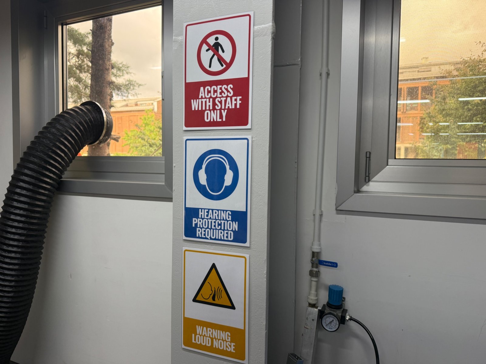
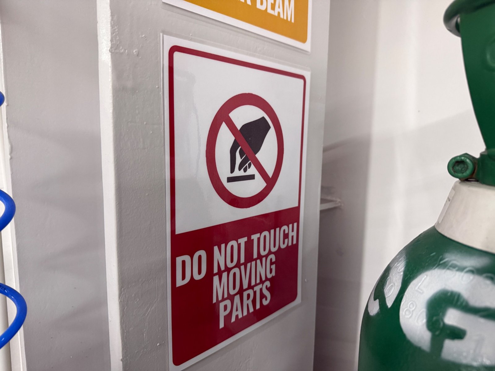
Before operating the CNC router, we reviewed the lab rules and the safety signs around the machine. The machine has a moving gantry, a high speed spindle, sharp tools, loud noise, dust and possible flying chips, so the CNC area can only be used after safety training.
The CNC area had clear warning signs for staff-only access, hearing protection, loud noise and moving parts.
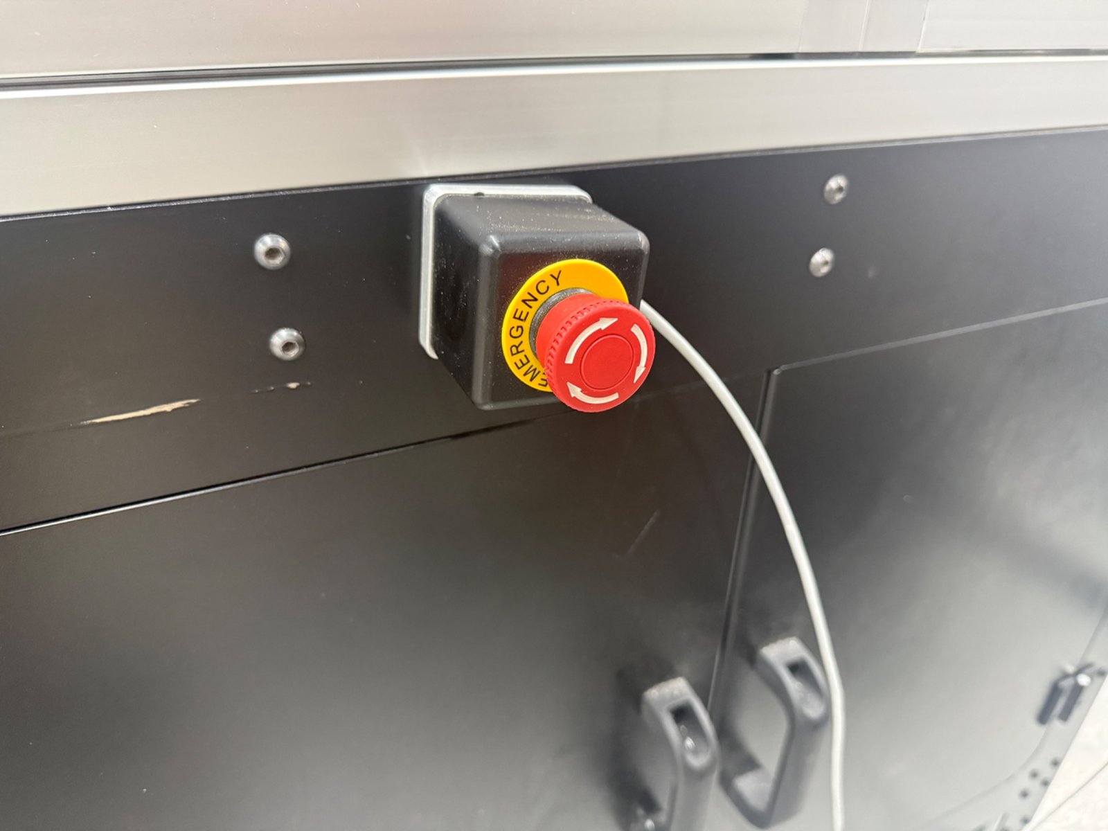
We identified the emergency stop button before starting the job. This is the first control to use if the machine moves unexpectedly, the tool breaks, the material becomes loose, fire breaks out, or any unsafe condition appears.
| Safety item | Rule followed in the lab | Reason |
|---|---|---|
| Eye protection | Wear safety glasses near the machine | Chips and dust can be thrown out by the cutter |
| Hearing protection | Use hearing protection when the spindle and vacuum are running | The CNC router and vacuum are loud |
| Hands and clothing | Keep hands, sleeves, jewelry and loose items away from the machine | The rotating tool and moving axes can catch loose objects |
| Machine access | Only trained users or staff operate the CNC | Prevents incorrect setup and unsafe operation |
| Door and distance | Keep the machine enclosure closed during cutting | Reduces risk from chips, dust and moving parts |
| Dust control | Use the vacuum cleaner and clean the bed after cutting | Plywood dust is messy and should not remain on the machine bed |
| Check | What we did |
|---|---|
| Material | Checked that the plywood was flat and large enough for the test file |
| Tool | Checked that the bit was inserted correctly in the collet and tightened |
| Toolpath | Checked that screws were not inside the cutting path |
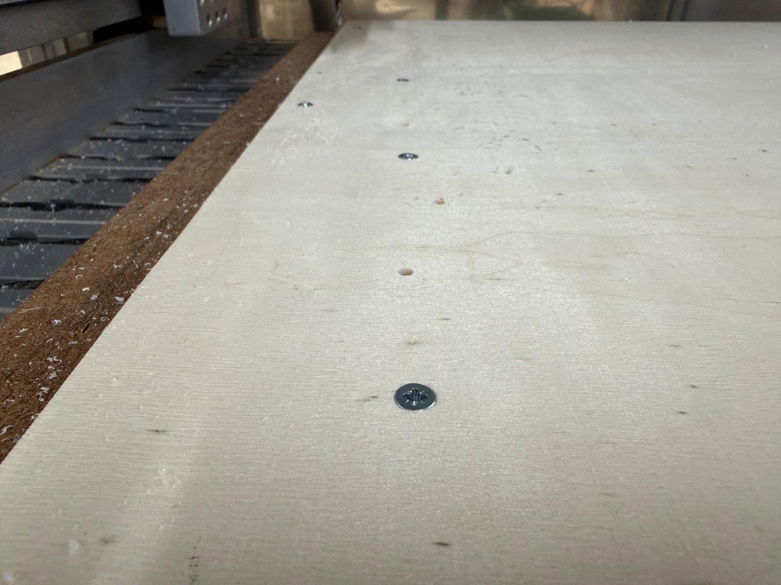
| Workholding | Fixed the plywood to the sacrificial board with screws |
| Origin | Set the work zero before running the job |
| Dust | Prepared the vacuum cleaner for chip and dust removal |
| Emergency | Located the emergency stop button before starting |
| Item | Detail |
|---|---|
| Machine model | Derinmotion Cube 3D |
| Machine type | CNC router with enclosed working area |
| Control software | UCCNC controller interface |
| CAM software | VCarve Pro |
| Workholding used | Screws into the sacrificial board |
| Dust collection | Vacuum cleaner |
| Test material | 0.8 cm plywood, approximately 8 mm |
| Test type | Slots, dogbones, feed-rate test, spindle-speed test and press-fit test |
We used an end mill mounted in an ER collet. Before cutting, we visually inspected the bit and the collet to make sure the tool was not loose or visibly tilted.
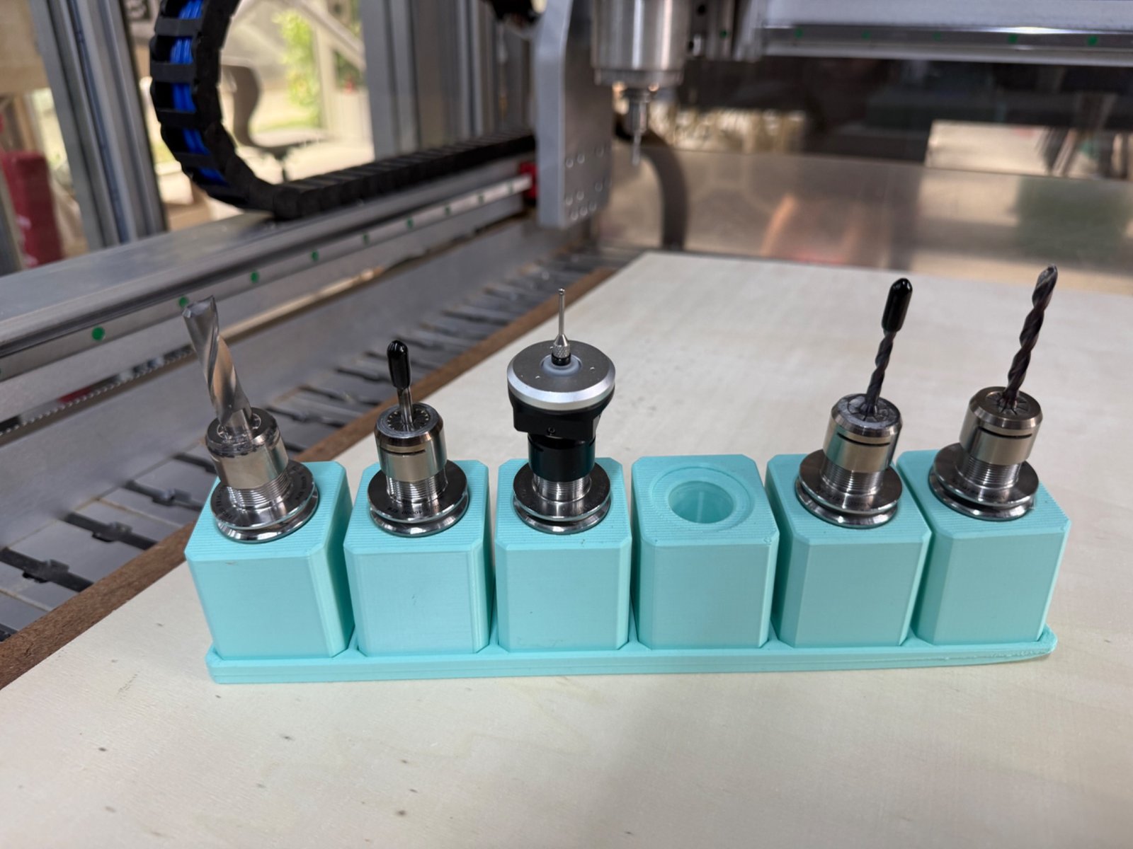
| Tooling item | Notes |
|---|---|
| Cutter | End mill for plywood cutting |
| Tool diameter used for dogbone geometry | 4 mm |
| Collet | ER collet holder |
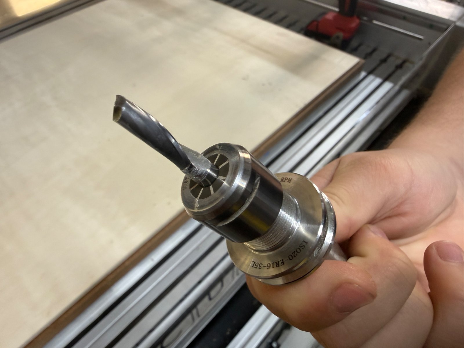
Runout is the unwanted wobble of the cutting tool while it rotates. Too much runout makes the cut wider, damages the edge quality and can break small tools.
For this test we did a practical runout check before cutting. We cleaned the tool holder area, inserted the tool into the collet, tightened it, then visually checked the tool tip while the spindle was prepared for operation. We did not measure the runout with a dial indicator, so this was a qualitative check.
| Runout check step | Observation |
|---|---|
| Tool inserted in collet | Tool was held straight and tightened securely |
| Visual inspection | No obvious wobble was observed |
| First cuts | Slots were cut consistently without visible tool wandering |
| Limitation | A dial indicator would be needed for an exact runout value in mm |
Alignment was checked by placing the plywood flat on the bed and aligning the test strip with the machine axes. After setting the origin, we checked that the toolpath stayed inside the material and away from the screws.
| Alignment item | What we checked | Result |
|---|---|---|
| Material alignment | Plywood placed flat on the sacrificial board | Acceptable for the test piece |
| X/Y toolpath direction | Test slots followed a straight line | No visible shift during the test |
| Z reference | Tool was set to cut through the 8 mm plywood | Full-depth cuts were achieved |
| Screw clearance | Screws were placed outside the toolpath | No collision with screws |
For this test the plywood was fixed with screws. This was important because the test slots were through-cuts, and any movement would affect the press-fit result.
| Fixturing method | Advantage | Risk or limitation | Result |
|---|---|---|---|
| Screws into sacrificial board | Strong and simple for plywood | Toolpath must avoid screw heads | Worked well for the test |
The test design was prepared as a 2D cut file and opened in VCarve Pro. The design included rectangular slots, dogbone corners and repeated test sections for comparing feed rate, spindle speed and press-fit clearance.
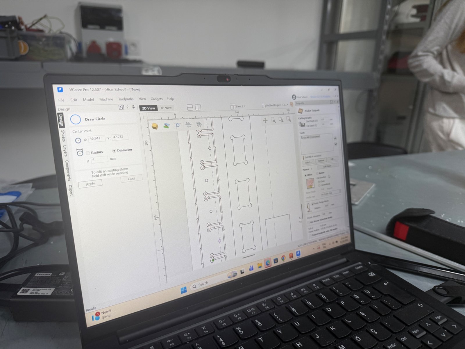
The toolpaths were created as profile cuts. Dogbone reliefs were added because a round end mill cannot make a perfectly sharp internal corner. Without dogbones, a rectangular plywood tab would hit the rounded inside corner and would not seat fully.
| CAM setting | Value used in the test |
|---|---|
| Material | 0.8 cm plywood |
| Cutting type | 2D profile cut |
| Cut depth | Through cut for 8 mm plywood |
| Corner strategy | Dogbone reliefs |
| Toolpath goal | Compare cutting quality and press-fit behavior |
| Output | CNC controller file loaded into the machine interface |
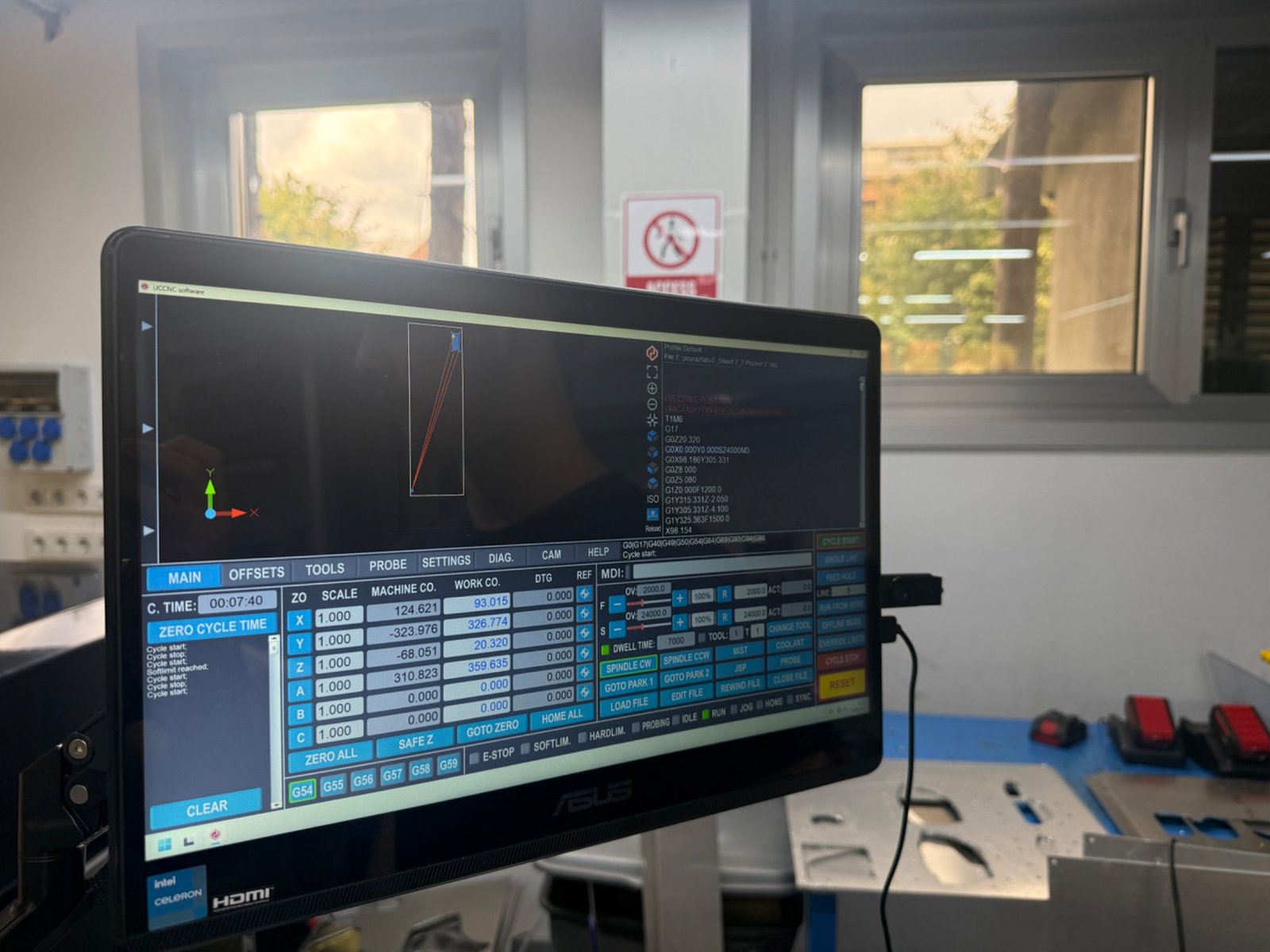
After the machine was set up, the plywood was cut on the CNC router. The machine followed the toolpath and cut the slot samples while the plywood remained fixed to the bed.
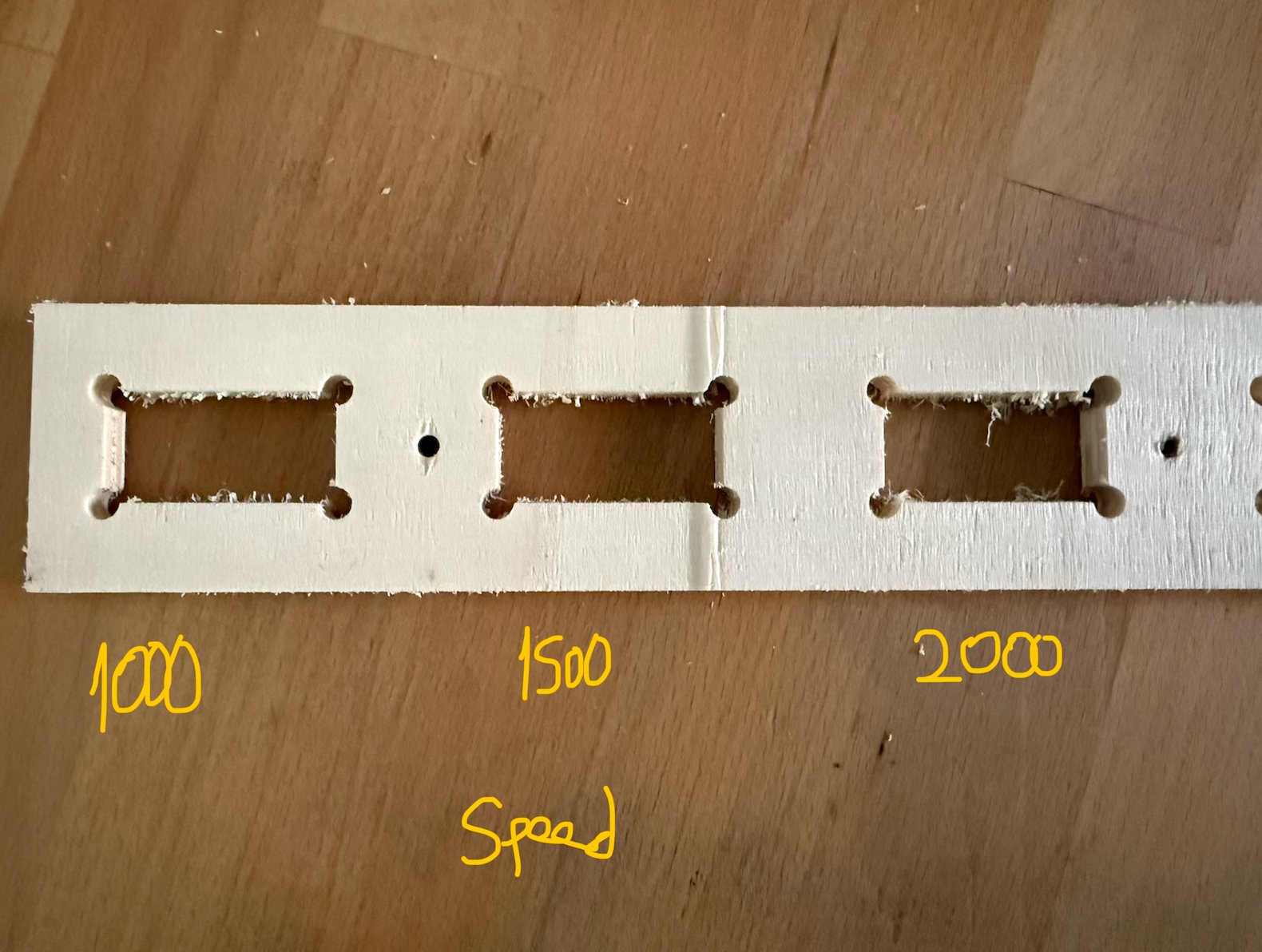
For the first comparison, we kept the spindle speed constant and changed only the feed rate. The tested feed rates were:
For comparison, the chip load can be estimated with:
chip load = feed rate / (spindle RPM x number of flutes)
The following chip-load values assume an 18,000 rpm spindle speed and a 2-flute end mill. They are used only to compare the settings.
| Feed rate | Spindle speed | Estimated chip load, 2 flutes | Observation | Result |
|---|---|---|---|---|
| 1000 mm/min | 18,000 rpm | 0.028 mm/tooth | Slowest cut. The machine was stable, but the edge still had plywood fibers. | Usable, but inefficient |
| 1500 mm/min | 18,000 rpm | 0.042 mm/tooth | Best balance between cutting time, stability and edge quality. | Selected reference feed |
| 2000 mm/min | 18,000 rpm | 0.056 mm/tooth | Fastest cut. More visible fuzzing and roughness appeared on the slot edges. | Usable, but not the cleanest |
The 1500 mm/min feed rate was the best compromise for this plywood test. It was faster than 1000 mm/min but still cleaner and more controlled than 2000 mm/min.
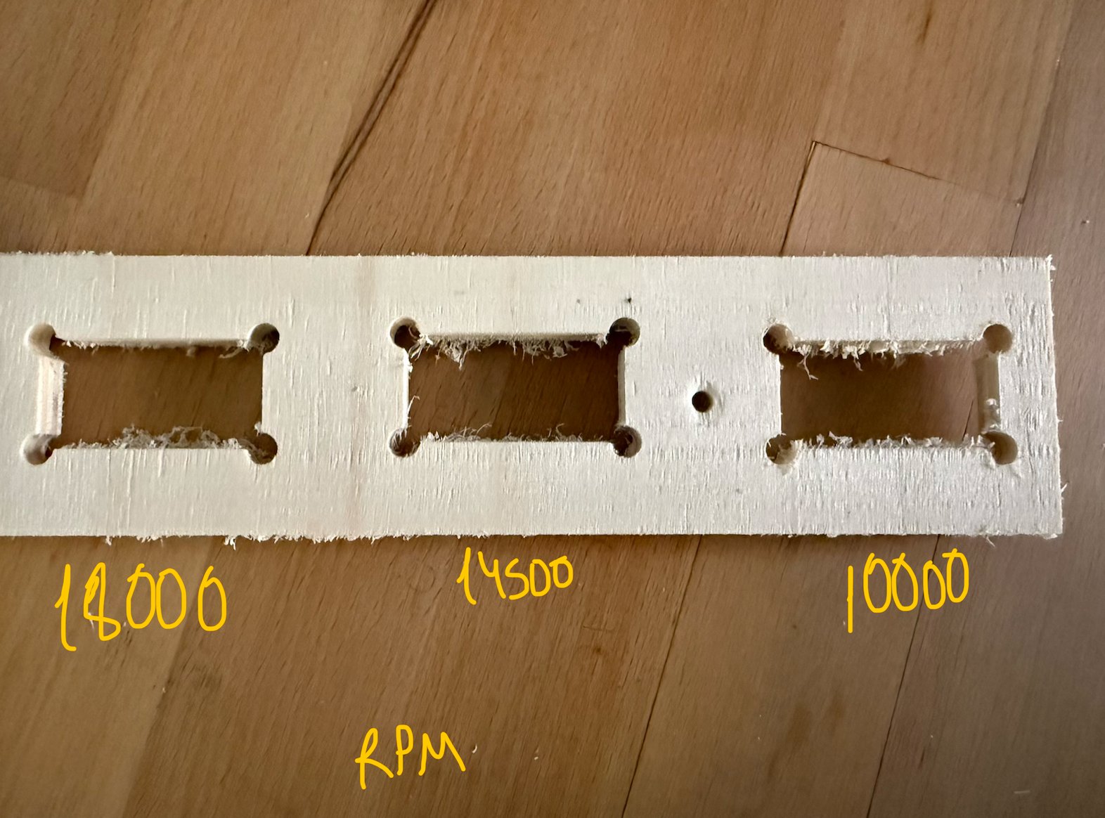
For the second comparison, we kept the feed rate constant and changed only the spindle speed. The tested spindle speeds were:
The following chip-load values assume a constant feed rate of 1500 mm/min and a 2-flute end mill.
| Spindle speed | Feed rate | Estimated chip load, 2 flutes | Observation | Result |
|---|---|---|---|---|
| 18,000 rpm | 1500 mm/min | 0.042 mm/tooth | Smoothest and most consistent result in the test. | Best result |
| 14,500 rpm | 1500 mm/min | 0.052 mm/tooth | Acceptable cut, but the edge quality was slightly rougher. | Acceptable |
| 10,000 rpm | 1500 mm/min | 0.075 mm/tooth | Rougher edge and heavier cutting behavior. | Not preferred for this test |
For this plywood and toolpath, 18,000 rpm gave the cleanest result. Lower spindle speeds increased the chip load and made the cut rougher.
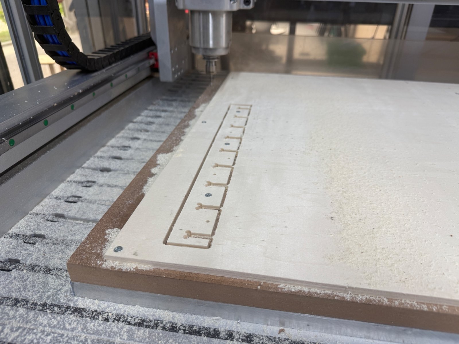
The final part of the test was a press-fit clearance test for the 0.8 cm plywood. We cut a comb-like test piece and tried fitting a plywood sample into the slots.
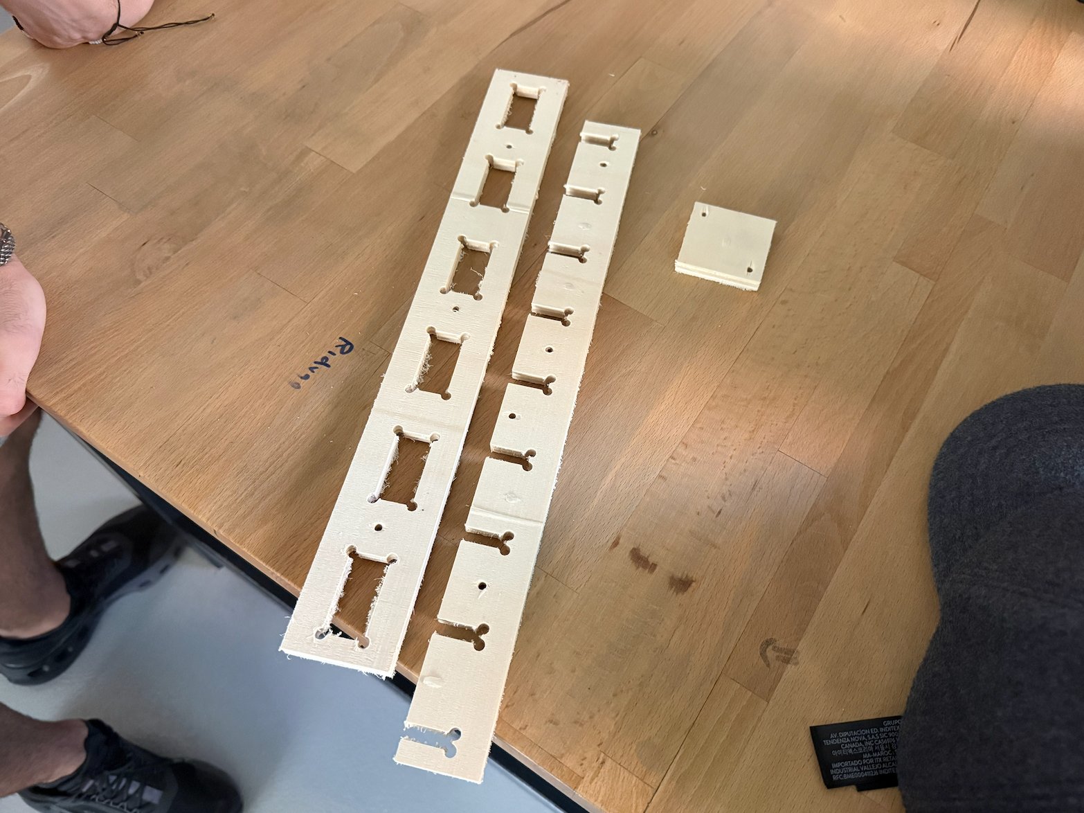
![]()
| Clearance setting | Fit result | Comment |
|---|---|---|
| Less than 0.78 mm | Too loose | The joint did not hold tightly enough |
| 0.78 mm | Best fit | The part seated well and had the best press-fit behavior |
| More than 0.78 mm | Did not fit properly | The joint became too tight in our test convention |
The best clearance for this batch of 0.8 cm plywood was 0.78 mm. This result is specific to the material, tool, machine and setup used in this test. If the plywood thickness, tool diameter or machine changes, the clearance should be tested again.
| Parameter | Recommended value from our test |
|---|---|
| Material | 0.8 cm plywood |
| Machine | Derinmotion Cube 3D CNC router |
| Toolpath type | 2D profile cut with dogbones |
| Workholding | Screws into sacrificial board |
| Dust control | Vacuum cleaner |
| Feed rate | 1500 mm/min |
| Spindle speed | 18,000 rpm |
| Press-fit clearance | 0.78 mm |